
As in my previous blog post described, the angle limit of my self-made faceting head had to be adjusted manually. Although there is a coarse and fine adjustment it is hard to reproduce formerly set angles, also it is quite time consuming and cumbersome. I therefore decided to use an electronically controlled motorized construction that should speed up the handling of the cutting angle significantly. I demonstrated the result already in a video clip:
In this post I want to give more details about how the applications works in detail. Note, that this is a report about the status quo after I successfully tested the whole thing with a quick test cut. I plan to continuously improve the construction if necessary.
The control unit user interface
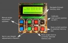
Currently six out of the eight present buttons are activated. I reserved two for a possible future extension, when I probably will use a second stepper motor to adjust the height of the slide on a new mast. In this case the thing will work quite the same, except that not only the angle will be controlled, but also the height of the slide.
I use 3 lines of the 20 characters by 4 line LCD display. The first line always shows the actual position of the angle limit. The second row shows the currently selected memory slot. Each memory slot can save one angle position. I configured the software to have ten memory slots available. During faceting the recalling of a previously used angle can be done quite simple and fast with using the saved angles in the memory slots.
The bottom line is used to display the touch degree as some kind of scale from left to right.
Components used
- Arduino Uno
- I2C LCD Display controller; Using the I2C interface only two output ports of the Arduino are used to control the LCD.
- 20x4 LCD Display with backlight;
- CNC Shield for A4988; Shield capable of holding four A4988 stepper motor controllers. In my case only one is used. Beside the 5V logical voltage also the motor power supply (between 8 and 35V) is connected. I use about 19V.
- A4988 Stepper Motor controller
- NEMA 8 0.6 A Stepper motor, full-step controlled (i.e. 200 steps per cycle, M4: 0.7mm per rotation); Tiny stepper motor with a maximum current of 0.6A. I operate it in full step mode rotating an M4 threaded rod with 0.7mm per rotation. That gives a movement resolution of 0.0035 mm per step, which should be sufficient in my case. The length interval of the 90° movement is about 55mm, so in theory and in average one motor step equals about 0.006° angle movement.
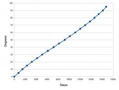
Calibration
As this construction is not a linear movement, but a combination of linear and radial movement I decided to calibrate by measuring the needed steps for a set of sample angles using a digital angle protractor. I started with 0°, then 5° ... up until 95°. In the software I wrote a short linear interpolation for values between the calibration samples. Here you can see that due to the radial movement the connected calibration points result in a slight wave.
Backlash
In any mechanical construction more or less backlash must be expected. In this construction I luckily could avoid any unintended movement of the rotating wheel and the rod holding the touch sensor by using my lathe for exact fittings and self fixing nuts. But, there is backlash in the threaded rod pushing and pulling the limitor as well as in the fixing screws of the motor. To achieve a highly accurate position reproducability I made sure by software that the target position is always approached from the "pull direction", meaning lifting the angle limit upwards. So, for the case the limit is moved downwards, the stepper motor goes 200 steps further down than targeted and immediately 200 steps up again. This indeed ensures maximum reproducability of previous positions.
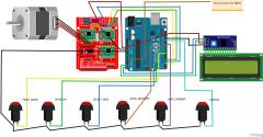
Wiring Plan
Here I documented the most important wiring of my construction. I did not add the power sources. Practically it is the common USB plug of the Arduino for the logical 5V and an old laptop power supply (19V) for the stepper shield.
Software
Last, but not least, the program that drives the whole stuff. Please note that the calibration values from my specific construction are hardcoded. Also hardcoded are the stepper motor delays that I figured out during playing around with my motor and the current limit of the A4988. For other applications, these values for sure have to be determined separately.
One open todo I still do have open. For the anyhow binary information if the touch sensor reports "touch" or "no touch" I should for performance reasons rather use a digital input, and not an analog as it is now. Alternative would be to have some kind of smoothened circuit using a capacitor so that I can omit the ring buffer and directly read a meaningful analog value. But so far, so good: faceting_angle_control on GitHub
As soon as I have some experience with using this new angle control in practice I will report!