
I recently finished one of my long term projects that I had in mind for quite some time before I started. Essentially some ideas I had already after I finished my first self built faceting head (described here).
Beside a better quality and reliability this faceting head should fulfill the following requirements:
- Better stability
- The joints and connections between the parts should be more firm
- It should be more "massive" in order to eliminate vibrations
- Higher accuracy
- Arm should be fixed and rotations and movements should not allow any play
- Angle change should happen on an exact perpendicular movement
- Index wheel and needle should provide solid fitting, stability, and accuracy
- Small in size
- As the name indicates the size of the faceting head should stay as small as possible for the least demand of space
- Good "usability"
- Fast and accurate change of angle limit
- Fast and easy change of rotation index
- Although arm is fixed, a good view on the stone should be possible
All of that I tried to consider in my design here's the video presenting the outcome:
In the following I'd like to share some details that were not part of the video:
Parts used
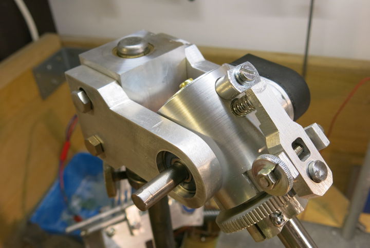
You might have seen that many of the self designed parts I milled or turned out of aluminium. I simply bought some left overs from a close metal dealer and used my low cost (and self CNC'd) milling machine and lathe to create arbitrary parts. The axis and rods however are steel shafts. Beside that I bought some ready made parts:
- ER16 Chuck Holder with 10cm shaft
- Usually used for milling, but a good solution to hold the dop stick. Also allows to hold dop sticks of different diameters. (However, I use 8mm only so far)
- Graphite Lubricating Brass Bushings
- These are a nice option for my use case. However, I cut the ring axially once to allow putting pressure on it by a grub screw. This way there's no play.
- Optical incremental encoder sensor
- This piece was one of the more expensive parts (EUR 18,-). The nominal resolution for a full rotation is 1000 ticks. However, using the signal edges more intelligently, it does 4000 ticks. This results in a 0.09° accuracy, which is sufficient. Note that I took the idea from the great book of Tom Herbst: Amateur Faceting
- Arduino Electronics
- I chose an Arduino Mega 2560 (Just to keep it extensible. A simple Uno would do as well)
- 20x4 characters LCD display with an I2C middle piece
- ... and a lot of M4 / M3 screws, nuts, and threaded bars
Software
My Arduino sketch is kept quite simple, altough I invested quite something in performance tuning in order to have a fast reaction time of the display. If you are familiar with C than it shouldn't be hard to understand the code, it's also commented well.
The sketch is available at https://github.com/techworkrocks/arduino_compact_faceting_head. I used two libraries:
#include <Wire.h>
#include <LiquidCrystal_I2C.h>
If they are not already coming with the Arduino IDE, they should be easy to find on the web.
Construction Plans
This time I collected all single files that I used to feed my CNC mill. I used Inkscape (SVG/DXF) and EstlCam to mill. The actual design I did with the great tool Blender.
I did not publish the files (yet) as they are not "polished" by now. Please contact me via email (see here) in case you are interested in having these.